
Shanghai Expo 2010 Megastructure, Building, Pavilion, Image, Architect, Design, News
Shanghai Expo Building : Expo Axis
Megastructure Architecture 2010 – design by SBA GmbH with Knippers Helbig
31 Mar 2010
Megastructure – Expo Shanghai 2010
Architect : SBA GmbH
Concept
Location. Competition. Development
The Expo site is located at the Huangpu River west of the town centre Pudong. The Expo Boulevard and the main part of the Expo – national and theme-based pavilions, as well as innovative urban concepts – Better City, Better Life – are based on the south side of the river. In 2007, the concept of an open entrance and boulevard building, embedded in the landscape, took the architecture firm SBA, Stuttgart / Shanghai into the final round of the international competition for the entrance-building of the Expo 2010 in Shanghai.
The design concept comprises a compact structure to accommodate all required public facilities, such as box office, security gate, restaurants, shops and central allocation points. The 1,000 m long and 100 m wide axis is lowered by twothirds into the ground. Spacious lateral slopes flood the floor levels with light and air. This creates a large-scale terrace on the building, which was originally planned to be covered with a wide-span roof comprising a glazed grid shell with triangle meshing. Knippers Helbig Advanced Engineering supported SBA since August 2007 by developing the structural system.

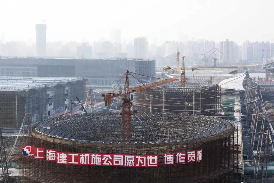
photo : Knippers Helbig
Nine mega columns comprising a glass-steel framework bear the main load while rows of slim pillars support the edge of the roof. In a preliminary scheme, the glass roof structure has been optimised in design studies. The main emphasis was on the reduction of the pillars and on adapting the mega columns to the modified space allocation plans. Approximately three months after the start of the planning stage, the basic conditions had changed. Consequently, the client requested the planning of a membrane roof instead of a glass structure.
A decision was then made in favour of a solution retaining the Sun Valleys, which are vital for the concept, and featuring a spacious supplemental membrane roof. This way, the Expo Boulevard stands within the tradition of Stuttgart’s internationally respected lightweight constructions, which was first established in the German Pavilion by Frei Otto at the Expo 1967 in Montreal.
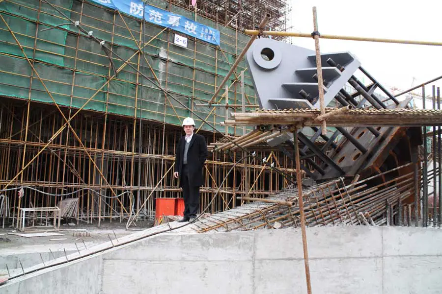
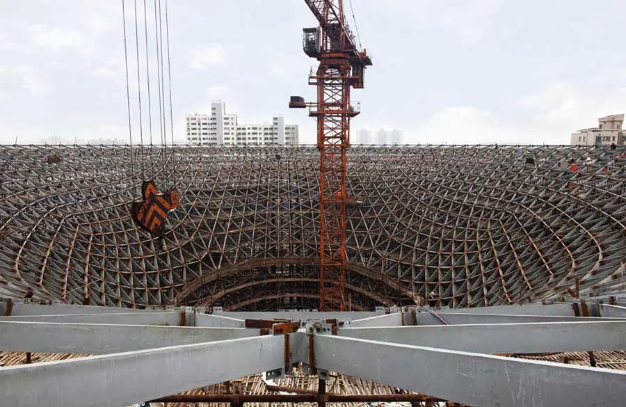
photo : Knippers Helbig
The membrane roof obtained its current shape in three fundamental steps of development: The structuring of the large scale triangles is not only taking static demands into consideration, but also numerous constraints by streets, bridges and tram stations, which had already been allocated in the layout. This overall planning also had a restrictive impact on the height of the exterior columns and the steep back stays. With their wind suction cables and hangers, the centre masts minimize the distortion of the membrane under wind load and bear the major part of the vertical loads, as well as uplifting loads. The inner connection rings and double layered membrane serve for load distribution and reinforcement of the membrane at the load concentration of the inner low points.
Membrane
Static Concept. Structure
The membrane roof covers a surface of 65,000 m2, of which about 5,000 m2 are double layerd. The applied PTFE-glassmembrane is of the sturdiest type V and has a tensile strength of 8,000 N / 5cm, which is equivalent to 16 t relating to a strip of 1 m width. The minimal pretension level was set to 2.5 kN / m. The static concept is mainly characterised by the combination of the exterior masts and the inner low points between which the membrane spans.
They are complemented by wind suction cables in the plane of the membrane between the high and the low points and the hangers, which are fixed to them to prevent the membrane from collapsing. The head of the centre masts are linked to the exterior masts by safeguard cables. The inner masts, which have a diameter of 600 mm, take a major part of the vertical loads. They carry steel rings to which the main membrane and the wind suction cables are fixed. Each connection ring is held in place by an outer staying of the centre mast. 3 x 4 hanger cables and the three head cables meet at each mast head.
Every exterior mast is anchored by two back stays with a diameter of up to 160 mm. These dimensions are commonly used for bridge constructions. Gravitation foundations, resting on poles, have a cube side length of up to 8 m and provide sufficient mass to anchor the tensile forces of the cables, which can partially be far beyond 1,000 t. The approximately 2 m x 2 m large bases of the back stay plates are fixed to anchor rods, and can be readjusted during the first months, according to the relaxation of the membrane. The space underneath the bases will be covered with concrete just before the opening of the Expo.
There are up to nine main cables connected to the head of a mast. The membrane is fixed to each Sun Valley at a couple of points in order to fit it tightly around the funnel. The reliable transition of the bearing loads at the back stays and at the foot of the masts posed a particular challenge, because every modification of the geometry implies a change in the distribution of forces within the membrane. The fact that the design of the solid building and specifically the infrastructure underneath had already been setting the scene, made it feel like redeveloping an existing building – not an easy task concerning such a complex roof.
The static calculations put two matters at the centre of consideration; the cables and the membrane. A failure of these two components, i.e. slacking, has to be precluded, also under unfavourable wind loads. Therefore, the pretension of the cables had to be optimised in an intricate iteration process, while the geometry of the stays and the support points repeatedly had to be altered. Particular attention was paid to the inner low point. The biggest loads and load peaks are concentrated at this point, which necessitates a double-layer construction. ’Excess tensions’ were systematically identified in analysis. On the architects request the double-layered membrane was designed as a rosette, which comprises eight leaves in most of the low points. Numerous geometry optimisations guarantee that the radial forces do not exceed the limit values and assure a minimal tension level in the direction of the rings at all times to prevent draping.
The head and the foot of the masts consist of cast steel GS20, mounted on ball bearings. The heads of the masts are varying and were intensely assessed in 3D visualisation and mock-ups. The connection plates are partially up to 2 m long to avoid the collision of fork connectors. The shaft of the mast head and the connection plate are made of one cast to simplify the assembly of the masts. Particular importance was attached to the transformation of the eccentricities resulting from the large connection plates in combination with wind loads. These cause immense local moments in consequence of cable and axis displacements, which were determined for every single mast head. The detail design of the connections of the membrane to the Sun Valleys is geometrically complex. Double-joint connections prevent the application of unscheduled moments resulting from angle modifications due to wind load.
The roof structure basically drains the water to the inside and towards the inner masts. While planning the details, great emphasis was set on achieving preferably slim and reduced aesthetics to counteract a visual accumulation of components at this intricate detail. The integration of the drainage in the mast has proven to be a condition for a proper design of the lower joints of the mast cable truss. The main membrane is fixed to the inner ring. An additional membrane of the type II, which is significantly more flexible, constitutes the link between the inner ring and the lower drainage point, the feed hopper. Thus, the main membrane is more than four meters away from the visitors; and backwater or packing of snow can not cause damage on the main membrane. Four tubes with a diameter of 200 mm lead from the feed hopper to the output at the foot of the mast. From there they are directed past the base plate to the solid building. The foot of the mast rests on a ball bearing and features a welded protection against uplift forces.
photos : Wilfried Dechau, Stuttgart
Sun Valleys
Shape. Geometry. Structure
The six Sun Valleys each have a surface of approximately 5,000 m2. The diameter at the foot is approximately 16 m and at the upper edge 80 m. The surfaces were optimised in several iteration cycles according to static and design aspects. Generating the triangular grid states an interpretation of the principles of dense packaging and multifunctionality as Buckminster Fuller has applied to the US-Pavilion for the Expo 1967 featuring the geodesic dome. In this respect, the sun valleys follow the same approach as the membrane, in terms of natural structures – minimal use of material. The triangular grid is the result of two basic considerations: For geometric reasons the number of triangles has to increase significantly from bottom to top and the main line layout has to follow-up the main force direction in order to achieve the most efficient structure. Therefore, the lines at the foot are directed in a vertical direction and at the upper edge in a circular way. To accomplish this, 5-way and 7-way nodes have been inserted half way up to rotate the grid by 30 degrees. The number and positions have been selected according to a homogenous grid spacing of approximately 2.20 m.
Besides dead load, snow, wind and earth quakes, the loads of the membrane are of vital importance for the Sun Valleys. The calculation of the dependencies between the steel structure, the Sun Valleys and the membrane has been done in two steps. First, the spring rigidity at the local load application points has been conveyed to the membrane calculation by using reference loads. Then, the resulting membrane loads were considered and validated in the calculation of the sun valleys. As expected, it became clear that the Sun Valleys can well accommodate the almost tangentially applied forces from the membrane. Thus, the rather high local loads from the membrane only reflect in local bending moments; and therefore in deforming. This is the reason why only local expansions of the framework structure were necessary. To do this, the members in the periphery of four fields around the load application were continuously hunched. The standard cross-section of 180 x 65 mm expands locally to 500 x 140 mm.
The members were assorted in groups and the cross-sections were adapted according to the loads. Hence, approximately 48 cross-sections were developed and installed in an optimised way. These are composition profiles made of longitudinal welded flat steels. Grading the sheet thickness made a precise adaptation to the load situation possible and the heights of the cross-sections could be minimised. The optimisation went hand in hand with setting-up the member system. The vertical main lines at the shaft and the circular main lines at the upper edge exactly mirror the respective main directions of the normal force. Therefore, also solid profiles can be efficiently used in suitable positions. The definition of permissible distortions was set by Chinese Experts together with authors of the Chinese standard rules. In this process, the distortion limits for glass were of major relevance.
Summary
Engineering Architecture. International
A close Chinese-German cooperation was necessary from the very beginning and in all design stages of the Expo Boulevard. The initial design of the competition was further developed in several steps until the final concept was drawnup. During that time, several meetings in Shanghai were necessary, not only to discuss the development of the design with the client, but also to convince the Chinese consultants of the feasibility of the structure. As typhoons commonly visit Shanghai during summer months, discussions were always focused on the stress and distortions under wind loads. Extensive tests in the wind tunnel were therefore of particular importance. These tests were run at the Tongji University to determine the wind loads and flow values. Beyond this, a more then 20 m long mock-up of the roof structure has been built in China to asses the stress and distortions of the structure under various loads by using load cells and displacement transducers. At the same time, the failure of single back stay cables has been simulated to examine the behaviour of the system in such a case. The bearing capacity of highly stressed detail points, such as edge clamps and membrane reinforcements has also been verified in several big operational mock-ups. These experimental case-studies are surprisingly enriching for European Engineers, who usually rely to a large extent on computer calculations.
The development of the project was passed on to Chinese hands when the general geometry, as well as the essential details of the roof structure were developed and the feasibility had been verified by static calculations and accompanying tests. Whereupon, the structure has been realised almost as developed by Knippers Helbig. The design and the realisation of the roof is exemplary for a successful German-Chinese cooperation.
Expo Shanghai 2010 – main page with images
Megastructure – Expo Shanghai 2010 : Building Information
Client: Shanghai World EXPO Land Holding Co. Ltd., Shanghai
Architects: SBA GmbH
Overall concept: SBA GmbH Shanghai / Stuttgart, Li Hong und Bianca Nitsch
Membrane roof and sun valleys: Knippers Helbig Advanced Engineering, Stuttgart / New York
Managing partners: Prof. Dr. Jan Knippers, Dipl.-Ing. Thorsten Helbig
Contributors: Florian Scheible, Florian Kamp, Dirk Richter, Roman Schieber, Johannes Beran
Cooperation: ECADI, Shanghai, China
Energy scheme: Scholze Consulting, Leinfelden-Echterdingen, Germany
Gross floor space: 280.000 m2
Surface of membrane: roof 65.000 m2
Span: 100 m
Surface of free-form member system: 30.000 m2
Dimension boulevard: 100 x 1.000 m
Realisation period: 2006-10
Megastructure – Expo Shanghai 2010 images / information from Knippers Helbig Advanced Engineering 310310
Knippers Helbig Advanced Engineering are based in Stuttgart, Germany
Location: Shanghai, China
Shanghai Architecture
Shanghai Architecture Designs – chronological list
UK Pavilion Shanghai Expo – information from 30 Mar 2010
British Pavilion Shanghai Expo : further information
Shanghai Expo 2010 Design – Spanish Pavilion
Shanghai Building – Selection
Shanghai Expo 2010 Pavilion : Denmark
Shanghai Expo designer – British Pavilion UK Winner : Heatherwick Studios
Shanghai Expo UK Pavilion – information re RIBA visit
Comments / photos for the Shanghai Expo Megastructure Architecture page welcome